UA-45749527-1

Labels

Showing posts with label German Bikes. Show all posts

Tuesday, May 5, 2015

R1200GS Major Service

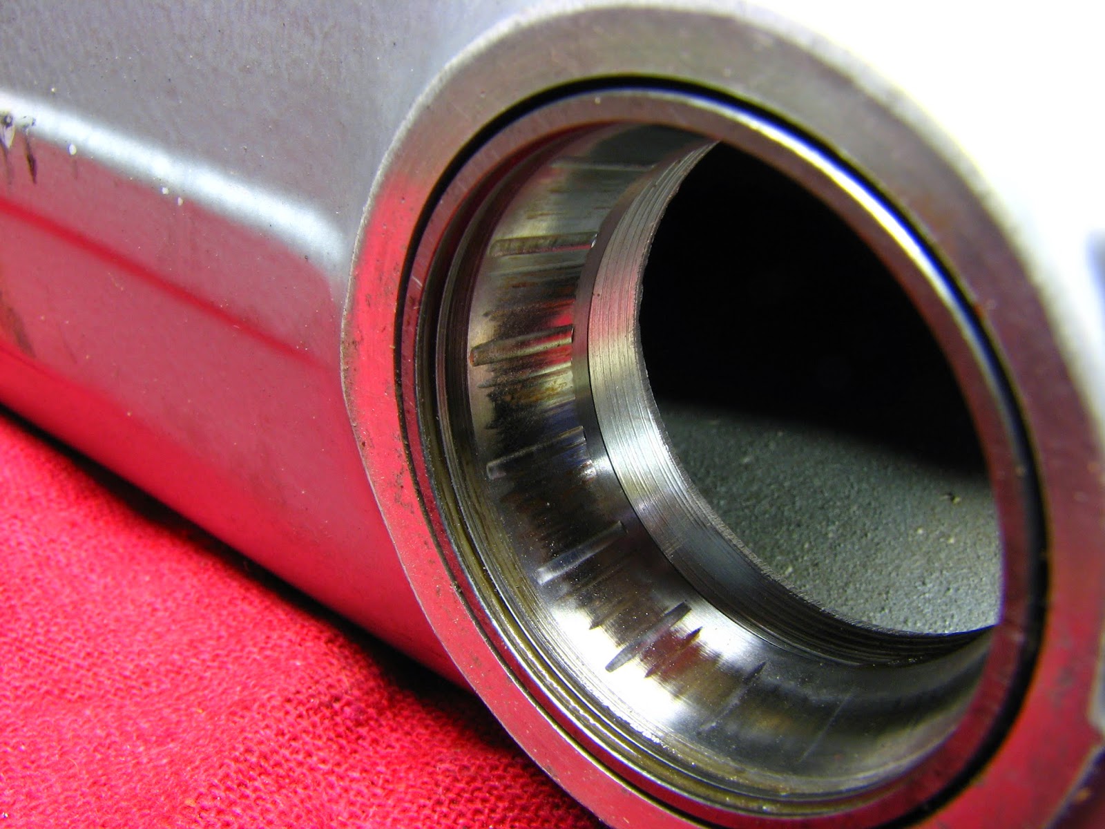
This 2006 R1200GS has 60 thousand miles on the clock and is in for a major service, input spline lube and general going-over.  The bike is equipped with BMW's Servo-Assisted ABS which will also be serviced with new fluid since the fluid has never been changed.  

So far, with the exception of the output shaft seal and a cracked swingarm boot, everything looks OK.

The clutch hub and input shaft splines are in good shape.


Oil leaking past the output shaft seal.


Tuesday, March 17, 2015

BMW R1100R 100-Thousand Mile Service

Here is an R100R that recently (4000 miles ago) had the clutch replaced at a local BMW dealership.
Apparently they missed a few things while it was apart and those items will be detailed here.
Keep in mind that until now the bike had always been serviced by the same dealership, at the factory recommended service intervals, which makes what I found all the more inexcusable.

This is the point to which the bike needs to be stripped to replace the clutch.

Starting from the final drive (which is the first component to be removed) we find that the outboard Paralever pivot bearing was seized which caused the inner race to destroy the pivot pin.

This is the outer race from the outboard side.  Obviously both bearings and the outboard pivot will be replaced.

The final drive seal was also leaking and was replaced.

Moving up to the swingarm pivot we find that both swingarm pivot bearings are failed.

The above items are things that any competent mechanic should have checked and found during the course of the clutch replacement procedure.

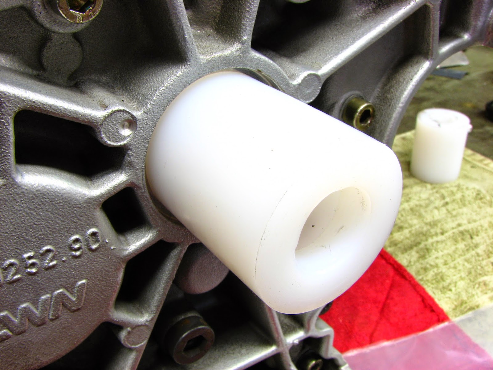
Since the transmission is out of the bike and considering the mileage, the transmission was resealed and the clutch release bearing, spring and boot were replaced.   BMW transmission seals do not rely on a shoulder to seat against, so they must be installed to their proper depth using a shouldered driver.

The input shaft, note the spline wear at 100K miles

Resealing the output shaft

All of the rubber parts will be replaced (right down to the battery strap) since they are subject to age-related deterioration.  The bike is also getting a set of Wilber's shocks to replace the OEM dampers that are well past their best days.


Saturday, September 27, 2014

Scrambler?.... Cafe Racer?.....

...Yes, it's both, or maybe neither, but it is pretty cool. 
It started life as a 1976 R75/6 that now wears dual-plugged heads,  BMW 336 performance cam, Dyna coils and electronic ignition, bobbed stock mufflers and many other custom touches.  The bike's owner did the vast majority of the custom work including the paint.  Motorrad Werkes handled the engine and chassis mechanical work for this one-of-a-kind project.  The owner is justifiably proud of his creation and we thought the finished product was worth sharing.


Monday, May 5, 2014

The moment of truth....

Today was dyno-run day.


Here are the results.
Almost 52 pound-feet, at 3500 RPM with 22 degrees total ignition advance (via restricted advance weight movement) and the cylinder head temp simply would not rise past 275 degrees Farenheit on the dyno.  This is with small valves, small carbs, stock everything except the combustion chamber mods.  The bike feels very similar to my K100RS 2V in the way it responds to throttle and is completely ping-free.  Oh yeah, everything between the head gaskets has 117,000 miles on it.


I think that the combustion chamber modification has been a successful experiment.  I will post fuel economy numbers once I get tired of playing and actually ride it responsibly.


Sunday, April 13, 2014

Airhead update

Well, it's back together and running.  I am waiting on an appointment for some dyno time to get some hard and fast numbers and more precisely dial-in the ignition timing for MBT.  In the meantime here is a short video clip.  The bike is rolling at 3000RPM and the throttle is simply opened quickly, no bouncing, tugging or any other "help".  It's completely stock from head gasket to head gasket, with stock intake and exhaust systems.

The bike has much-improved bottom-end and midrange and is utterly ping-free.  I fully expect to also see a major improvement in fuel economy.

Wednesday, March 19, 2014

At the flowbench

The chambers, seats and finally the ports are finished.  What follows are some photos and video that may be interesting to some of you.

Here is a head set up to measure airflow through the intake port.

 For my purposes there is no need to have the entire intake tract set up with the head, but we do need to make sure that the air enters the intake port in a smooth stream that is repeatable from head to head.  Some guys will use a clay bellmouth on the intake stub but I doubt that I could sculpt a perfectly matching bellmouth on two heads so I simply machined one from nylon.  It snaps right on and I put a dab of clay on either side to make sure that it stays put.

Here are some photos of airflow visualization using smoke.  The way the bellmouth turns the airflow can be plainly seen.


I have been experimenting with wet flow visualization, in the following videos you can see that at valve lifts of .100", .200" and .300" the new combustion chamber contours act as very effective half-diffusers and keep the airflow attached to the head around the entire periphery of the valve head while also enhancing intake flow swirl.  As we know, a properly designed diffuser converts the flow's velocity back into pressure with minimal flow loss.  The flow in the original configuration was mostly straight across the top side of the valve in two very strong streams that tended to travel straight across the chamber with no swirl.  I am much more concerned with flow velocity at the lifts between closed and full-open than I am about flow numbers at full-lift.  Think about this, with a cam that has a symmetrical profile, the valve will see every stage of lift twice (once on opening and once on closing) while it sees full-lift at one point and then only for an instant.  This is why it is not well to get hung up on obtaining maximum flow numbers at full-lift.  Remember, the flowbench is an abstraction, as no piston-engine sees prolonged steady-state airflow at full-lift.  The flowbench is best employed as a comparative tool.   The fluid that is used for visualization is much heavier than gasoline and so tends puddle a bit but the airflow visualization is accurate and there is no explosion hazard (life is stressful enough).


There is one other item to take care of before reassembly and dyno-tuning, that is the crankcase breather system.  The engine's crankcase volume is fairly small and that, combined with the fact that it fluctuates by an amount equal to the engine's displacement twice every revolution, tends to push a considerable amount of oil out of the crankcase breather.  While it is common knowledge that subjecting the crankcase to a vacuum is beneficial, the way BMW chose causes more grief than it's worth.  Venting the crankcase to the airbox and using intake vacuum to evacuate the crankcase results in the engine ingesting a not insignificant amount of oil.  As we all know, ANY oil ingestion is highly detrimental as it dilutes the incoming fuel-air mixture, helps set the stage for detonation and is the primary cause of combustion chamber coking that airheads are famous for.  Pull the intake elbows from any large-bore airhead and you will find this.
That is engine oil dripping from the crankcase breather pipe (which itself is quite an obstruction to airflow).  I am not an advocate of removing the airbox (since the intake length is beneficial to this engine), but this crankcase breather system (along with the pulse-air exhaust injection system) is going to go.  I will use a catch-tank plumbed in series with an electric vacuum pump.  This should keep a negative pressure(vacuum) in the crankcase regardless of the piston position, give the oil control rings an easier life and maybe free up some power, but most of all, NO MORE OIL IN THE COMBUSTION CHAMBERS.


Wednesday, March 5, 2014

Volume check

The last part of the combustion chamber modification is to measure and equalize the volumes.  The target volume was 80cc which will yield a compression ratio of 10.0:1.  The right cylinder head measured at 79.9cc while the left head came in at 78cc and so needed some adjustment to be equal to the right head.

That's it for the combustion chamber modifications.  Next will be the port work, which I will detail here.  Here are the finished chambers.

Friday, February 28, 2014

New guides and someplace to sit

Installing the valve guides:
Here is the shop-made driver that drives on the top shoulder of the guide, it is piloted and counterbored so as to miss the sharp-edged, tapered portion at the top of the guide.


The guides were reamed and honed to proper size and then the valve seat counterbores were machined.

The seats were machined from C63000 bronze.  This material is a superb heat conductor, has a similar expansion rate to the aluminum heads and is hard enough for unleaded use.  They are machined to a .007" interference fit in the heads and radiused (.062") so as not to broach any material when installed.

The heads are heated to 400 degrees F and the seats are frozen before being driven into place.
Here is a photo of the shop-made driver, note the o-ring to hold the seat in place on the driver.

Once the seats are installed they are contoured to match the combustion chamber shape.

Then the actual seating surfaces are cut (as well as a 60 degree back-cut and 30 degree top-cut) and zero seat runout is verified using a shop-made runout gauge.


Here are a couple photos of the runout gauge and a pilot.

Next step is to match the combustion chambers for volume (cc'ing) and then many fun-filled hours at the flowbench working on the intake and exhaust ports.